Reconstruct the aircraft
Trace visible contours, build CAD and compare the result back to its source. The current shape uses NASA’s SR-71 drawing, with uncertain features and missing sections kept explicit.
 OpenSR-71
An independent engineering project
From NASA’s three-view drawing to a model you can explore.
Building the connection between aircraft geometry, propulsion and differentiable simulation—one checked result at a time.
Work in progress — source-based reconstruction, not a validated digital twin.
See the limits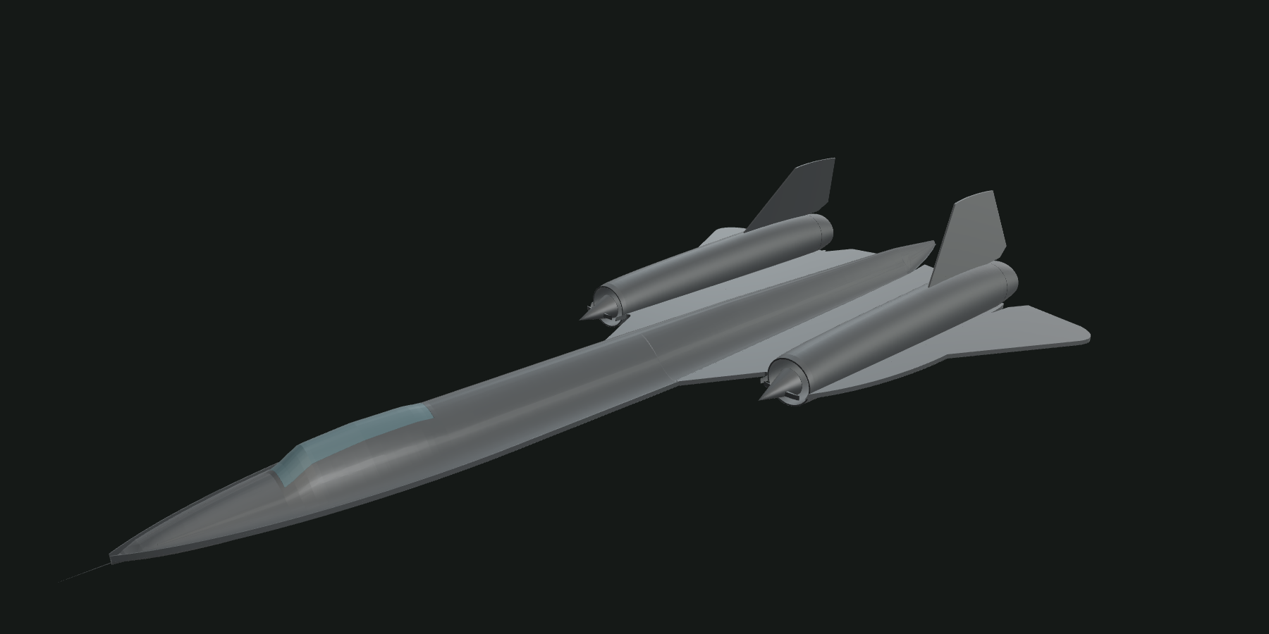
The visible mesh comes directly from the checked CAD export. Shape, installation and operating mechanisms still have unresolved engineering gaps.
Static geometry. View controls change the camera, not the aircraft’s operating state. CAD and research datasets are available by request.
The work behind the view
Trace visible contours, build CAD and compare the result back to its source. The current shape uses NASA’s SR-71 drawing, with uncertain features and missing sections kept explicit.
Develop running-engine and inlet models, track mass and energy, and retain failed cases. Compressor, inlet and nozzle behavior need more than a convincing animation.
SymPy supports the equations; JAX supports numerical models and derivatives. Source identities, test conditions and original failures stay attached to each experiment.
What the model can claim
The visible outline was rebuilt against a NASA SR-71 three-view. These comparisons measure agreement with that drawing. They do not establish aerodynamic, structural or historical accuracy.
Read the NASA sourceSix Decades of Flight Research · printed page 455
Graphic 980065 · captioned “SR-71”
The viewer loads the mesh tessellated from the reimported, checked STEP export: 10 component groups, 128,358 triangles. Export integrity is a software check, not proof of physical fidelity.
The drawing has no printed scale or production tolerances. Side and front heights conflict; hidden junctions, internal structure and engine installation remain unresolved. The low canopy suggests an A-form aircraft; a specific serial or configuration is not established.
Distances in original reference-image pixels. Both directions are shown: source outline to CAD outline, and CAD outline to source. These are comparisons to construction artwork, not independent validation.
| View / direction | RMS | 95th | Max |
|---|---|---|---|
| Plan · source → CAD | 2.98 | 7.02 | 15.13 |
| Plan · CAD → source | 3.68 | 9.70 | 16.87 |
| Profile · source → CAD | 1.23 | 2.18 | 3.97 |
| Profile · CAD → source | 1.74 | 2.90 | 15.16 |
| Front · source → CAD | 3.23 | 6.19 | 8.41 |
| Front · CAD → source | 3.60 | 7.37 | 15.45 |
Some errors remain worse: plan CAD-to-source 95th-percentile distance rose from 8.69 to 9.70 pixels. The profile maximum remains 15.16 pixels. There is no overall accuracy percentage or all-metrics pass.
Reference contours follow the raster ink edge. CAD contours are sampled projections; source scaling, provisional datums and tessellation add uncertainty. No historical acceptance tolerance has been established.
For researchers & collaborators
Interested in the CAD, the experiments or contributing to the project? Share what you want to explore.
Research files and CAD downloads remain private. Requests are reviewed individually; this page does not grant access.